Best Practices - BLK2FLY
BEFORE SCANNING
This document will help new users of BLK2FLY scanner system to familiarize themselves with currently known best practices. Following
best practices will help scanner users to perform scanning operations in most efficient and safe way.
For detailed step-by-step workflow please refer to BLK2FLY user Manual.
TAKE OFF & LANDING AREA REQUIREMENTS & PREPARATION
Take-off area is a really important place while you’re executing the UAV mission. Remember that your platform will record location of this
point as a Home Point. In case of any connection loss or BLK2FLY will return and land at this point autonomously.
Important things to note when selecting and setting take-off location:
• Watch out for moving object in proximity as people, cars, trucks, etc. Predict any potential hazards in advance. BLK2FLY obstacle avoidance
• Take-off area is at levelled surface. Small (10-15°) slope can be tolerated.
• Avoid Taking off from following surfaces.
» Grass
» Loose gravel
» Dusty places
» Dirt
If there is no alternative take-off/landing location in required area, landing mats can be used.
• Keep take-off/landing within reasonably close distance to the object of interest to have shorter transit paths and higher efficiency.
• Keep uninvolved persons away from take-off/landing area as well as scanning area. Security personnel or physical barriers are highly
recommended to be used where UAV can fly very low while scanning.
• Before RTL is executed, make sure it is safe
• Before you take-off, wait few seconds till RTK will get fix position. (Refer to the indication Icon in telemetry bar).
• Avoid setting late-off & landing location in areas with expected no or poor GNSS signal reception. This may negatively affect BLK2FLY
positioning during take-off and landing.
FLYING BEST PRACTICE
PREPARATION:
• Keep batteries within set temperature limits of +10C to +35C before flight.
• » Do not leave batteries on direct sunlight or in hot environment to avoid overheating.
» During cold months keep battery in warm place till it is used for flying.
• It is recommended to use fully charged batteries for flying
• Complete pre-start checklist
• Plan upcoming flight
» Inspect the object you want to scan. Think about the way you want to scan it and find a location that allows you to keep direct line
of sight with the drone during the whole flight
» The range of measurements of the lidar is:
- Minimum 0.5m
- Recommended 3.5 – 6 m
- Maximum 25 m
» Take into account the collision avoidance “Bubble”. Check for any obstacles potentially not detectable by obstacle avoidance system
» Plan the flight considering the maximum single battery flight time is 13 minutes, including take-off, mission, return and landing and
power safety buffer (3 minutes).
• Start BLK2FLY Live app on iPad
» Connect iPad to BLK2GO
• Check airspace information for potential hazards or restrictions using in-app live airspace map.
• Check in app settings
» Flying speeds
» Set low battery failsafe mode (RTL, RTU or Land)
» Set geofence (If required)
» Scanning parameters (Speed, Spacing)
• Ensure all required parameters are as expected. Use extended telemetry bar in flight screen. No warning messages
» Signal Strength
» WLAN connection
» LTE connection (if applicable)
» GNSS/RTK position
TAKE OFF & MISSION START:
• Keep correct UAV orientation. Front of UAV should face away from the Pilot during take-off.
• Use Joystick or smart controls to navigate BLK2FLY in 3D Space
FLYING:
• Operator shall always keep direct line of sight with BLK2FLY in the air.
• Operator can change his position during the flight to ensure good eye contact with BLK2GO is maintained. Take extra care when moving
around – lookout for surrounding hazards.
• Operator should use available toolset of UAV position and orientations controls:
» Virtual Joystick – universal tool to control 3D position and orientation of BLK2FLY.
- Requires some experience for comfortable use
- Fast and efficient way of controlling BLK2FLY
» Tap-to-Fly – can be used for sending BLK2Fly to desired point on 3D map. Scanner will reach selected point automatically
avoiding obstacles.
- Good for changing UAV position from one structure or façade to another one autonomously
- Object has to be previously scanned.
» Pan Camera View – BLK2FLY will yaw automatically.
- Useful tool when planning Live Image mission. Yaw the Scanner to pick required points on bigger facades
» Zoom in/out Camera View – BLK2FLY will fly forwards or backwards automatically, avoiding obstacles
STAGES OF THE FLIGHT & TERMINOLOGY USED:
FLIGHT – duration while UAV is in the air from moment of take-off until landing. Flight can contain one or multiple missions.
MISSION – autonomous part of the flight planned by user.
SCAN – single scan is acquired from the moment it is started automatically at mission start or manually triggered by user. Scan is finished
when “Stop Recording” is triggered by user or at landing.
CURRENT LIMITATIONS:
Certain limitations apply to locations where BLK2FLY can be operated. Scanner cannot be flown:
OBSTACLE AVOIDANCE
Obstacle avoidance is a feature which keeps BLK2FLY away from detected real-world objects during the flight. Obstacle avoidance works
both with manual and automatic flying modes. Obstacles are not only detected, but also bypassed if safe flight trajectory can be calculated
by BLK2FLY.
Best way to understand obstacle avoidance – imaginary “bubble” or 3.5 m radius around BLK2FLY. See picture below.
Note the “blind” areas for each type of sensor.
Obstacle avoidance can be switched off by user. While obstacle avoidance is switched off, sound alarm will be enabled to remind user.
Normally, obstacle avoidance should be switched on all time. However, in certain situations it temporary switch off is tolerable:
• BLK2FLY is “stuck” in between obstacles and cannot leave it’s position.
• If BLK2FLY must be flown faster than 2 m/s. Switched off obstacle avoidance will allow maximum speed of 5 m/s.
Can be used for:
» Accelerate return in low battery case scenario
» Accelerate return in low battery case scenario
» Flight area must be left immediately
» Faster transit between different locations
Obstacle avoidance should be immediately switched on after require action are completed. Obstacle avoidance will automatically switch on
if any autonomous flying mode is triggered automatically or by user input.
RETURN & LANDING
There are several methods of landing BLK2FLY:
• Manual return followed by triggered “Land In Place”
» For experienced users familiar with “Virtual Joystick” controls
» Fast and efficient way of ending the flight
• Automatic return to landing. BLK2FLY will automatically return to its’ pre-recorded take-off position.
» Fully Autonomous. No user interaction required after it’s is triggered
• Automatic return to user. In this case BLK2FLY will get current location of an iPAD and set it’s landing location there. After RTU is
triggered, Pilot should move away 3-4 meters and monitor the process of landing. Due to low accuracy of iPAD GNSS position, actual
landing position may be shifted from real world position. Pilot may need to adjust position manually.
» Useful for scenarios when desired landing position is away from take-off location.
• Land-in-place. Aircraft will descend vertically down and land.
» Used as last stage of manual return to landing
» If flight needs to be finished immediately
» Obstacle avoidance will be off during Land In Place execution of final vertical landing stage of other return modes.
» Fully manual landing is not supported. User has to execute land-in place to land aircraft. Emergency switch shall not be used for landing.
» User can adjust the position of the BLK2FLY applying joystick input during “landing” stage.
» Also, landing can be cancelled at any time by user.
DATA ACQUISITION BEST PRACTICE
CURRENT LIMITATIONS
Due to the nature of Lidar and slam technologies currently certain limitations exist. BLK2FLY may not achieve desired scanning quality with
following objects types listed below. Current GrandSLAM algorithm cannot guarantee satisfying results.
» Metal “cage” type structures, such as powerline masts or communication towers
» Structures with a large number of round surfaces, such as water tower or silos
» Facades with a high amount of glassy or reflective surfaces.
» Large-scale objects, with dimensions exceeding 100 m
GENERAL DATA ACQUISITION RECOMMENDATIONS
These general recommendations are applicable to every scanning project, independent of scanning mode.
1. Always try to scan object within single scan if they can be done within duration of single flight. Continue recording when switching
between different surfaces and elements of the structure. However, the scans can be split by users if no registration( linking) is planned
to be done in future.
2. When using BLK2FLY rule of thumb can be applied “better scan more than less”. Redundant data will improve final data quality.
3. Scan overlap between adjacent scans should be at least 40%.
4. If there is battery life left after completing planned mission, use it for extra scanning and extending coverage and overlap.
5. It is recommended to start and finish scan at the same point and same orientation, that is helpful for SLAM technology.
6. Keep data recording “ON” during Return To Land phase of flight.
7. The best performance of the platform is with default scanning settings
a. Live image mission: Distance to object=4m, line spacing=4m, V=2m/s
b. 2d map mission: Distance to object=4m, line spacing= 4m, V=2m/s
8. After scan is finished, it is recommended to fly back to landing location flying over or next to the surfaces which were not scanned
previously during the flight. Do not stop recording during this. This will make final scan more “rigid”. See example:
9. Review scan data after each flight. Review data in Project Browser Make sure desired objects are scanned as planned.
10. Scan Data Management. Naming data according to user-defined naming conventions helps in future with data processing and management.
11. Extend selection region when planning mission in Live View or 2D map beyond the edges of actual physical object. This help to scan data
beyond the corners. This approach will improve data robustises. Be sure that position of the last flight line, as in the following image, is
higher than the height of the façade and each flight line is extended beyond the facade to help the system to tight adjacent surfaces.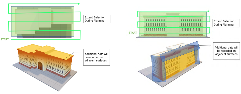
Same approach when scanning a roof, be sure that area to be scanned exceed the dimension of the building you want to scan.
COMBINING MULTI-FLIGHT SCANS
SCAN OVERLAP:
Sufficient overlap between 2 independent scans is very important for the success of future registration. Insufficient overlap may cause poor
alignment quality or even failure. Recommended target overlap value for adjacent scans is 40%, but higher overlap values are beneficial.
Overlap percentage defines amount of common areas acquired in adjacent scans compared to the overall scan area of both scans. User has
to visually assess building and define required patterns to achieve good results. This requires some scanning and processing experience. The
exact overlap values can be seen during alignment process. Examples:
Finishing the scan at the same spot where it was started, scanner having similar orientation. Processing algorithm will match the scanned
objects in the beginning and the end of the scan and adjust the recorded data to make It more robust.
Planning and making a good overlap is critical for a successful registration of the point clouds. Plan mission is such way that:
1. Overlap between the scans is 40% or more.
2. Adjacent Scans are at least linked in a loop.
3. Linking more scans in the group will improve registration quality.
SIMPLE BUILDING. 2 FLIGHTS:
The example of scanning simple shape building in 2 flights is shown below:
Although it may look that actual overlap is 33%, expanding scanning areas beyond physical surface limits will increase overlap to 40-50%
and increase overall robustness of future scan alignment.
For such mission combination of scanning modes can be used:
• 2D map mission to scan the roof
• Live Image Mission to scan the facades
• Optional manual scanning to fill any gaps in automatic scan coverage.
SELECTING SCANNING MODE
Every object is unique. User has to decide which scanning mode, or combination of modes to use in order to achieve best results in most
efficient way. Examples of applying various scanning techniques on a single structure:
• Live image mission:
» Building and structures with well defined large scale surfaces. The rule of thumb to use Live Image scanning – surface should be
at least 12X12 meters or equivalent (10X14; 6X18 etc.)
» Flat horizontal areas where 2D map mission is not possible due to missing or outdated map data
• 2D map mission
» Roof scanning
» Flat ground surface. Town Square, Parking etc.
» Earthworks on construction site
» Volume calculations- stockpiles, storage of raw materials
• Manual recording - joystick
» Structures with not well defined, or complex surfaces and edges.
» Small flat surfaces or structures.
(Rule of thumb: if building dimensions are less than 12x12x12 meters it is more efficient to scan manually.
» Structures or parts of the structure covered by obstacles. Manual scan will give user more flexibility to scan the structure.
» Large facades where Live Image mission cannot be automatically generated.
» Filling scanning gaps after automated mission is completed.
» Any other structure scanning scenario not supported by current automated flying modes.
» Environments, where user needs more control over BLK2FLY flying trajectory due to safety concerns.
• Manual recording - Touch to fly
» For users who don’t yet feel comfortable using virtual joystick to control BLK2FLY
» Small buildings/objects of interest
» Filling scanning gaps after automated mission is finished
SCANNING EXECUTION
LIVE IMAGE MISSION:
For scanning the building in the image, select Live Image Mission planning for facades and 2D map mission planning for the roof.
BLK2FLY has to be in the air in order to start live Image mission planning process.
Automatic flight mission generation is based on 3D map data and live image from onboard camera. BLK2FLY combining this information to
calculate the plane of required surface.
1. Before starting planning, manually position BLK2FLY in front of the facade. Optimal distance to start planning is 10-15 meters from the
surface. This will ensure sufficient scan data is collected, so that surface 3D plane can be determined. 3D map can be checked to verify.
2. Pilot manually selecting points on the surface do define edges of the scanning area by selecting points on the building surface.
At this stage BLK2FLY orientation can be adjusted. But position must remain static.
3. Automatic mission 3D path is generated. It is recommended to check 3D path viewing it in 3D view.
» Pilot can trigger autonomous flight execution or
» Pilot can plan another area. Position and orientation of the scanner can be adjusted if needed
After mission is completed, it is recommended to continue recording until landing. However, recording can be stopped if another isolated (no
scan alignment planed) structure needs to be scanned
2D MAP MISSION:
Optimal Scanning parameters:
» Scanning Speed – 2 m/s
» Line Spacing 4 m
» Distance (height) to the object of interest 4-6 m
1. Tap on the “plus” button and select Area Recording.
2. Area recording does not require any scan data for planning, therefore it can be planned while BLK2FLY is still on the ground.
3. Multiple scanning areas can be planned for single flight.
4. Select area/areas that you want to scan
5. Set the flying height. Flying height is set relative to the height of take-off position. BLK2FLY will follow target height, and adjust it if there
is an obstacle on the way
6. Confirm each scanning area by pressing “Tick” for app to generate flight path.
7. Execute scanning. Monitor scanning process
8. After scanning is completed, and UAV has landed review the scan data by opening it in Project Browser. Make sure all required objects
are scanned
TIPS:
• If required height is unknown or hard to estimate BLK2FLY scanner can be manually flown to required height. Mission planner will use
current flying height for defining the target flying height.
• For roofs or areas which are uneven or include multiple level surfaces following options are available:
» Option A. Set height of 2D mission in relation to main (or lower) part of the roof. Flying height will be adjusted by obstacle avoidance
where needed.
» Option B. Plan multiple level scanning mission. Set flying height for each part of the building individually.
• While executing the mission, always visually follow the drone. Never lose the line of sight.
• If the area is challenging, you should ask for help the observer that can have line of sight with the drone when it is impossible for you.
You’ll still have the LTE connection with the drone.
MANUAL SCANNING:
Optimal Scanning parameters:
» Flying speed 2 m/s
» Distance to the object 3.5 - 6 m
Using manual scanning requires experience operating BLK2FLY using virtual joysticks, tap-to-fly and gesture commands. User shall be
familiar with all manual control modes, and execute the depending on the need
Planning automatic mission takes valuable flying time. For some small buildings may be not efficient. In that case it is recommended to
scan building manually. Rule of thumb is – when one of dimensions of the façade or whole building is less than 12 meters, it is more efficient
to scan building manually.
Requirements for manual scan:
» It is recommended to keep consistent flying patterns when scanning manually. For example, zig zag or spiral flying patterns
» Avoid fast excessive movements and yawing.
» Keep BLK2FLY within short range of the structure while scanning.
» Do not split single structure into multiple scans. Preferred way is to scan as much as possible in one scan
To achieve best results, when executing manual scan object of interest must be scanned keeping it in front of the lidar module –
density of scanned points is highest there. Optimal scanning distance must be maintained whenever possible.
The best way to ensure that all require data is captured during the scanning is to monitor 3D map view during scan and check collected scan
3D view in project browser.
3D map point cloud within 3D map view and Scan Preview within project browser displays reduced version(voxelized) of scanned points.
Algorithms are analyising points to exclude noise points from the process.
It represents the 3D environment as it is “seen” by BLK2FLY. Each voxel is 10 cm diameter sphere.
Related Articles
Best Practices
MicaSense Sensors enable you to capture great data. This article offers some basic guidelines to provide the best results. It covers the following topics: Mission planning, to ensure proper overlap When to best capture data to minimize ...Trinity Pro Activation Procedure and First Time Updates
Intro: Hello and welcome to Measur's knowledge base! In this article, we will go over how to get set up with a Quantum Systems account and activate your new Trinity Pro! Step 1: Create a Quantum Systems Portal Account Firstly, please set up a QS ...Installing a SIM Card in the BRINC Ball
Overview This guide outlines the steps and best practices for installing a SIM card into the BRINC Ball communication device. SIM Card Requirements Type: Micro SIM card Functionality: Must support voice and text Note: No SIM tray is required. ...AVSS Parachute User Manual
Download the attachment below to view the AVSS Parachute user manual for the DJI M300. The user manual contains information about the parachute, safety instructions, installation, battery/charging, firmware, operating procedures, maintenance and ...Environmental Conditions
Check the weather forecast for wind, rain, and temperature. Alternatively, QBase3D has a built-in weather forecast under "Tools" --> "Weather". Type your location and receive the forecast. This can also be used to calculate wind at time of flight to ...